Networking runs on methods and protocols that standardize communication. The OSI Model is a classic framework that clarifies how different software and hardware elements coordinate. It has layers that guide data flow from one system to another.
It gives structure to troubleshooting, design, and understanding of network operations. Understanding what exactly is OSI model and its purpose reduces confusion and enhances collaboration. Each layer is assigned a clear function, preventing overlap and duplication of effort.
So, here in this article we will discuss on what exactly is OSI Model, and different layers in the OSI model. Let us get started!
What Is the OSI Model?
The OSI (Open Systems Interconnection) Model is a conceptual framework that standardizes the way communication occurs between computing systems. It divides the networking process into seven distinct layers.
Each layer tackles specific tasks and communicates with the layer above or below it. That approach helps vendors create interoperable products and reduces chaos in network design.
Key Goals of the OSI Model
- Standardization: Offers a structured blueprint for system developers.
- Interoperability: Encourages products from different manufacturers to work together.
- Modularity: Divides network tasks into layers for clear oversight.
- Flexibility: Permits upgrades or changes in one layer without disrupting the rest.
- Troubleshooting: Simplifies problem identification by isolating issues at particular layers.
It rose to prominence through the International Organization for Standardization, which felt there was a need for a methodical approach to networking. Before this model, protocols and hardware often lacked clear structure. Adoption of the OSI Model brought order and stability to the field of network engineering.
Historical Overview and Purpose
Early networks were often built with proprietary protocols. Vendors created systems that worked only with their own solutions. Friction and incompatibility arose when different networks needed to exchange data. Engineers recognized the need for a common guideline.
In 1977, the ISO set out to propose a solution. That effort aimed to form a layered reference that would clarify the path data travels inside a network. Two proposals converged into what is now the OSI Reference Model. It took shape as a seven-layer design.
Though many networks today use the TCP/IP model more frequently, the OSI Model remains a bedrock for conceptual clarity.
Experts worldwide still rely on OSI layering to describe how bits and bytes move across cable lines and wireless signals. The purpose is not just technical.
It also fosters conversation between network professionals who might otherwise speak different “dialects” of technology. In simpler terms, the OSI Model is a universal translator that structures how data flows.
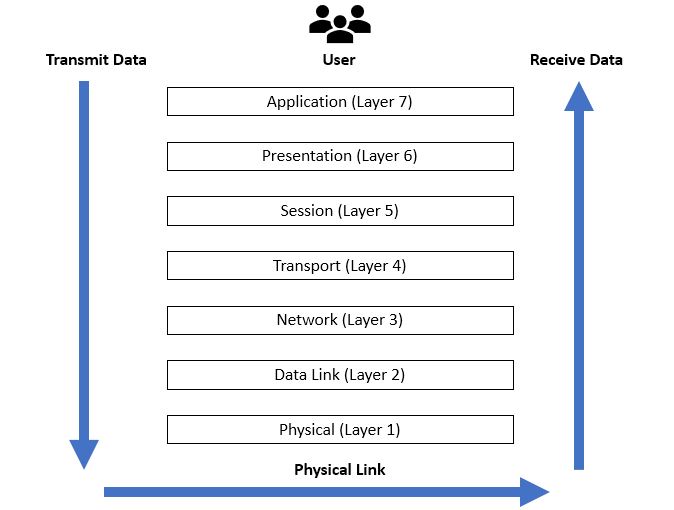
OSI Model: Seven Layers Explained
Below is a table summarizing each layer:
| Layer | Name | Main Role |
|---|---|---|
| Layer 7 | Application | Interacts with end-user software and provides network services. |
| Layer 6 | Presentation | Formats or translates data for the application layer. |
| Layer 5 | Session | Manages and controls connections between computers. |
| Layer 4 | Transport | Ensures data delivery, either reliably or not. |
| Layer 3 | Network | Handles routing and IP addressing. |
| Layer 2 | Data Link | Manages node-to-node data transfer and error detection. |
| Layer 1 | Physical | Deals with the physical medium and raw bit transmission. |
Layer 1: Physical Layer
Physical layer focuses on raw bit transmission. Electrical signals, radio waves, or optical pulses flow here. The job is to move data in the form of bits from one endpoint to another. Cables, repeaters, and hubs operate at this layer.
Typical Hardware
- Ethernet cables (Coax, Twisted Pair, Fiber)
- Wireless transmitters and receivers
- Repeaters and hubs
Practical Example
When a laptop sends data through an Ethernet cable, it generates electrical pulses. The Physical Layer ensures those pulses reflect the correct bit sequence. That sequence then travels to the receiver, which interprets them for the next layer.
Key Points
- Concerned with bit-level transmission.
- Includes voltage levels, pin layouts, and data rates.
- Has no awareness of packet structures; it only sees signals.
Engineering teams treat the Physical Layer as the foundation. For example, if a cable is damaged, data flow fails here before even reaching higher layers. It underscores the need for robust wiring and signal integrity.
Layer 2: Data Link Layer
Data Link layer handles node-to-node data framing. It organizes bits into logical frames and adds error detection and flow control. Devices at this layer decide which device can transmit data at any moment to avoid collisions.
Typical Protocols and Technologies
- Ethernet (MAC addresses)
- Wi-Fi (MAC-based transmissions)
- PPP (Point-to-Point Protocol)
- Switches and Bridges (operating here)
MAC vs. LLC Sub-Layers
The Data Link Layer is sometimes split into two sub-layers:
- MAC (Media Access Control): Handles hardware addressing (MAC addresses) and media access control.
- LLC (Logical Link Control): Controls error checking and flow.
Framing Process
Data bits from the Physical Layer become frames at the Data Link Layer. Each frame includes:
- Header (source and destination MAC addresses)
- Payload (the data)
- Trailer (error-checking info, such as CRC)
Error Detection: Cyclic Redundancy Check (CRC) is common here. If an error is found, the frame is typically discarded, and some form of retransmission request may occur, depending on the network configuration.
Example: Consider an office environment with Ethernet switches. Devices connect via cables, and each computer’s network interface card has a unique MAC address. The Data Link Layer decides when a device can send a frame. It also ensures frames are delivered to the correct MAC address.
Layer 3: Network Layer
The Network Layer determines how data moves between devices on different networks. Routing, addressing, and path determination take place here. Routers examine packet headers to decide which path a packet should take toward its destination.
Common Protocols
- Internet Protocol (IPv4 and IPv6)
- ICMP (Internet Control Message Protocol)
- IPsec (Security extension)
- RIP, OSPF, EIGRP (Routing protocols)
Routing: Routers maintain routing tables that map networks and possible next hops. When a packet arrives, the router checks the destination IP address and forwards the packet based on the best route. This helps data find a path even across networks separated by many nodes.
Addressing: IP addresses work at this layer to identify devices. A packet’s header includes source and destination IP addresses. That process differs from the Data Link Layer, which relies on MAC addresses for communication on the local network segment.
Fragmentation: Routers may split large packets into smaller fragments if the next network segment enforces a smaller maximum transmission unit (MTU). This procedure ensures that data fits the link layer constraints.
Example: When a user in one city visits a website hosted in another country, the data travels across multiple routers. Each router decides where to forward the packets next. That decision relies on IP routing protocols, which update routing tables.
Layer 4: Transport Layer
Transport layer focuses on reliable (or sometimes unreliable) end-to-end data delivery. It segments data from the session layer and ensures reassembly at the receiving end. Ports and connection parameters exist here.
Key Protocols
- TCP (Transmission Control Protocol)
- UDP (User Datagram Protocol)
TCP
- Connection-oriented.
- Provides acknowledgments, sequence numbers, and retransmission.
- Ensures data arrives in order, without duplicates.
UDP
- Connectionless.
- Simple and faster than TCP.
- No built-in mechanisms for reliability or ordering.
Port Numbers: Applications are identified by port numbers. For example, HTTP uses port 80, while HTTPS uses 443. The Transport Layer uses these numbers to direct data to the correct application process.
Flow Control and Congestion Control: TCP includes features to prevent network saturation. If a receiver is swamped, TCP will slow down the sender’s rate. If congestion is detected, TCP adjusts its sending pace to avoid dropping packets.
Use Cases
- TCP suits applications needing guaranteed delivery, such as file transfers or emails.
- UDP fits real-time applications like video streaming or online gaming, where occasional packet loss is less harmful than delayed packets.
Layer 5: Session Layer
The Session Layer coordinates and manages ongoing connections (sessions) between two devices. It sets up, maintains, and terminates these connections in an organized way.
Responsibilities
- Establishing sessions: Handshake procedures and setup tasks.
- Maintaining sessions: Handling data exchange once the session is active.
- Terminating sessions: Gracefully closing the connection to free resources.
Session Controls: This layer may include checkpoints or synchronization points. By inserting markers into the data stream, a session can be resumed from a certain point if a disconnection happens.
Examples
- NetBIOS sessions
- Remote Procedure Call (RPC)
- SQL session management
Software that needs advanced session control might use functions linked to the Session Layer concept, even if the protocols do not always match the OSI naming. The main idea is to keep track of dialog states, who is speaking, and how the conversation evolves over time.
Layer 6: Presentation Layer
The Presentation Layer deals with how data is represented and formatted. It transforms data to ensure that the application layer of one system can understand the data sent by the application layer of another system.
Key Tasks
- Data Translation: Converting from one character encoding to another (e.g., ASCII to EBCDIC).
- Compression: Reducing the size of data for faster transfer.
- Encryption/Decryption: Securing data before it travels on the network.
Practical Examples
- SSL/TLS encryption for secure web traffic.
- MPEG, JPEG transformations for multimedia data.
That approach ensures that sending and receiving systems handle data consistently. If one system uses a different data format, the Presentation Layer works as an interpreter, bridging those differences.
Layer 7: Application Layer
The Application Layer is the closest layer to the end-user software. It provides services that applications use to communicate over the network. This includes everything from email clients to web browsers.
Common Protocols
- HTTP (for websites)
- SMTP (for email)
- FTP (for file transfers)
- DNS (for domain name resolution)
Responsibilities
- Identifying communication partners: Ensuring the correct application is ready to receive data.
- Authenticating and privacy: Confirming user credentials or providing secure access.
- Data syntax and presentation: Interacting with the Presentation Layer to receive properly formatted data.
Examples: When someone types a web address into a browser, the Application Layer initiates an HTTP request. That request is handed off to lower layers for delivery. Once the server responds, the Application Layer in the browser processes and displays the results.
Differences Between the OSI Model and TCP/IP Model
While the OSI Model features seven layers, the TCP/IP model uses four layers. The latter is often used in real-world networking. Understanding both clarifies how data travels but from different angles.
| Aspect | OSI Model | TCP/IP Model |
|---|---|---|
| Layers | 7 (Physical, Data Link, Network, etc.) | 4 (Link, Internet, Transport, Application) |
| Development | Created by ISO for standardization | Evolved from ARPANET research |
| Usage | More theoretical reference | Practical and widely adopted on the internet |
| Transport Protocols | TCP or UDP at Layer 4 | Integrated at the Transport layer |
| Header | Separate headers at each OSI layer | Combined header for certain layers |
Key Observations
- The OSI Model is more detailed and serves as a teaching reference.
- The TCP/IP model groups some OSI layers (e.g., Data Link + Physical become the Link layer).
- When engineers mention layers in day-to-day operations, they often mix references from both.
Common Misconceptions about OSI model
1. OSI Model Is Outdated
Some might think it is obsolete, since the TCP/IP model is more prevalent. Yet the OSI framework remains helpful for conceptual understanding and troubleshooting.
2. Strict One-to-One Mapping
Not all real-world protocols map perfectly to each OSI layer. For example, SSL/TLS is often associated with Layer 6 or 5, but in practical terms, it can operate alongside application-layer protocols.
3. Only Software Layers
Hardware is sometimes overlooked. The Physical and Data Link Layers are intimately connected to hardware, such as cables, switches, and network interface cards.
4. Confusion with TCP/IP
The presence of separate layers for Session, Presentation, and Application can surprise those used to the simpler TCP/IP model. Both reference models are correct in their contexts.
Real-World Applications and Importance of OSI Model
Troubleshooting: When diagnosing a network issue, isolating the problematic layer saves time. If link lights are off, the Physical Layer might be at fault. If IP addresses are misconfigured, the Network Layer is the culprit.
Security: Firewalls often work at the Network or Transport Layer. Intrusion Detection Systems might monitor payloads in higher layers. Understanding these divisions makes security strategies more precise.
Protocol Design: Software developers often rely on OSI concepts when creating new protocols. They decide whether certain functions belong in the Transport or Application layer, for instance.
Better Collaboration: Communication among network professionals becomes more direct. Describing issues or solutions is clearer if everyone references the same layered model.
Bullet Points to Remember
- The OSI Model has seven layers: Application, Presentation, Session, Transport, Network, Data Link, and Physical.
- Each layer has specific responsibilities, and they rely on one another.
- Troubleshooting is simpler when each layer is understood.
- Physical Layer handles signals; Data Link manages frames and MAC addresses.
- Network Layer deals with IP addresses and routing; Transport covers TCP or UDP.
- Session manages dialogues, Presentation adjusts data formats, and Application is where user-level protocols live.
- OSI vs. TCP/IP: OSI is conceptual, TCP/IP is more common in real networks.
Example Use Case Flow
- Application Layer: A web browser forms an HTTP request.
- Presentation Layer: The data might be compressed or encrypted (TLS).
- Session Layer: A session is set up to maintain the web transaction.
- Transport Layer: TCP segments the data and decides when to resend.
- Network Layer: IP addressing and routing pick a path to the website’s server.
- Data Link Layer: Frames are formed with MAC addresses and error checks.
- Physical Layer: Bits travel as electrical or optical signals across cables or wireless channels.
On arrival, the process reverses. Each layer at the destination interprets the data, unpacks headers, and passes the payload up the chain.
Frequently Asked Questions
Q: Is the OSI Model used in day-to-day networking?
A: It is more of a reference. Networks often use TCP/IP for actual communication, yet engineers reference the OSI Model to describe or troubleshoot issues.
Q: Why does the OSI Model have seven layers?
A: Each layer addresses a unique set of concerns, ensuring no overlap. That separation encourages cleaner protocol design.
Q: Does encryption always occur at the Presentation Layer?
A: In theory, yes. In real systems, encryption can appear at multiple points, but it fits neatly into the Presentation Layer concept.
Q: How does Wi-Fi fit into the OSI Model?
A: Wi-Fi deals with the Physical Layer (wireless signals) and Data Link Layer (MAC frames). Higher layers remain the same across Ethernet or Wi-Fi.
Conclusion
The OSI Model is a valuable blueprint for networking discussions. It offers clarity by dividing tasks into layers with distinct functions. While the everyday internet often runs on TCP/IP, the OSI model’s seven layers provide structure for troubleshooting and training.
Problems become simpler to fix when each layer’s duty is understood. Future technology will continue building on these concepts, keeping the OSI Model relevant for years to come.
Also Read: